The Business Object-oriented Process Modeling Approach and Workflow Patterns
Abstract
The workflow patterns research work led by Wil van der Aalst and Arthur ter Hofstede result in the identification of 43 patterns that describe the behavior of business processes. The results can be used as a basis to examine the strengths and weaknesses of a particular language to process specification. This technical documentation provides a comprehensive evaluationof the business object-oriented process modeling approach such that how the workflow patterns can be represented by this approach.
1 Introduction
The research work led by Wil van der Aalst and Arthur ter Hofstede result in the identification of 43 patterns that describe the behavior of business processes [1]. The aim of this research is to evaluate the expressiveness of various approaches to process specification used as a basis for language and tool development. The original twenty patterns along with the twenty three new patterns form the new collection of workflow patterns associated with the control-flow perspective. The collection divides into eight classes of patterns namely basic control flow patterns, advanced branching and synchronization patterns, multiple instance patterns, state-based patterns, cancella-tion and force completion patterns, iteration patterns, termination patterns and trig-ger patterns.
This paper reviews how the business object-oriented process modeling approach can represent the workflow patterns from the control-flow perspective. We should assume at the beginning that the business process has only one business object with no interaction with other business objects, since workflow patterns associated with the control-flow perspective do not describe the interaction between processes. Since we have extended statecharts with actions and events to model the life cycle of the business object, the evaluation of a process specification with a single business object is equivalent to the evaluation of extended statecharts.
2 Basic Control Patterns
The first five patterns capture basic aspects of process behavior.
2.1 Sequence
The sequence pattern describes activities which are executed one after the other in sequential routing. The business object-oriented modeling approach uses states with a given order to describe this pattern as shown in Fig. 1. E1 is the event generated after the completion of the task in State1. C1 is the condition of the transition. A1 is the action of the transition. The business object stays in State1 until E1 occurs and C1 is true, at that time the transition from State1 to State2 is triggered. Then the task in State2 is executed. Note that the task is invoked on the entry action of a state.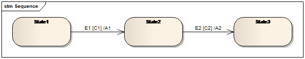
Fig. 1.Sequence pattern
2.2 Parallel Split
The parallel split pattern describes the split of a branch into two or more branches so that multiple activities can be executed concurrently. Figure 2 shows the parallel split pattern. We do not specify the ECA rules on the transition, since by default, the events are the completion of tasks in the source states. The exit condition of the parallel state is the completion of all the concurrent branches.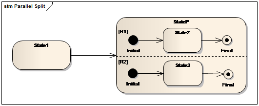
Fig. 2.Parallel split pattern
2.3 Synchronization
The synchronization pattern describes the convergence of two or more concurrent branches that are created using the parallel split pattern. By default, the exit condition of the parallel state StateP is the completion of all its concurrent branches. As shown in Fig.3, the synchronization is happened when both the tasks in State2 and State3 are completed.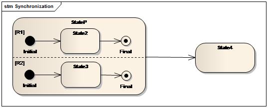
Fig. 3.Synchronization pattern
2.4 Exclusive Choice
The exclusive choice pattern describes the ability to choose one activity from several alternative branches based on a mechanism. As shown in Fig.4, which transition is triggered is depend on the condition on the transition.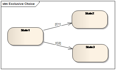
Fig. 4.Exclusive choice pattern
2.5 Simple Merge
The simple merge pattern is used to merge the alternative branches chosen in the exclusive choice pattern into a single branch. It differs from the synchronization pattern in that merging several branches without synchronizing them. The diagram is shown in Fig.5.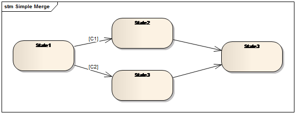
Fig. 5.Simple merge pattern
3 Advanced Branching and Synchronization Patterns
This series of patterns characterize advanced and complex concepts of branching and merging the flow of a business process.
3.1 Multi-Choice
The multi-choice pattern describes the divergence of a branch into one or more parallel branches based on a selection mechanism.The business object-oriented modeling approach provides a way to support the multi-choice pattern as shown in Fig.6. The Null state behind the initial pseudostate in each branch of the parallel state is the key point to implement this pattern. In state Null the business object does nothing but waits for an event (e1/e2). The action of the transition from stateA to MC means that sends e1 or e2 or both of them to the process model. When an event is sent, the variable sCount is increased by one. If e1 is sent, then e1 is handled by the first branch of the parallel state such that the transition from Null to State1 is triggered. The task in State1 is executed when entering State1. The variable fCount is increased by one when the task in State1 is completed. Note that the second branch stays in the Null state all the time since there is no e2 in the event queue. If both e1 and e2 are sent, then both of the parallel branches are selected. Therefore, as shown in Fig.2, any of the branches can be selected.
3.2 Structured Synchronizing Merge
The structured synchronizing merge pattern is used to merge the parallel branches selected in the multi-choice pattern that must be associated with the multi-choice pattern in the process model. The modeling challenge is that the number of parallel branches to be merged is not known at the design time. It is totally depend on the multi-choice pattern.From the description of multi-choice pattern, we can see that there are two variables that need to pay attention to. The variable sCount will be increased by one when an event is generated by the action of the transition from StateA to MC. The variable fCount will be increased by one when a branch is completed. Therefore the synchronization of results is executed when the two variables become equal. Then the transition from MC to StateB is triggered. Thus, as shown in Fig.7, any of the branches can be selected and synchronized.
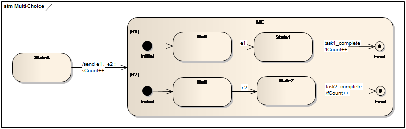
Fig. 6.Multi-choice pattern
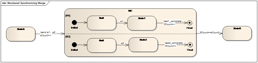
Fig. 7.Structured synchronizing merge pattern
3.3 Multi-Merge
The multi-merge pattern provides a means of merging multiple distinct branches into a single subsequent branch. It differs from the structured synchronization pattern in that there is no need to synchronize these branches when they are completed and the completion of each branch will instantiate the tasks in the subsequent branch one time. The multi-merge pattern must be associated with the multi-choice pattern which is appeared earlier in the process model.Actually this pattern is a little bit confused to me about the behavior of duplicate execution. Such duplicate execution of the subsequent tasks is not supported in the business object-oriented modeling approach. For statecharts, if a parallel branch is completed, it will wait for the completion of all the other branches before the processing of subsequent branches. Therefore the exit condition of the parallel state is the completion of all the parallel branches. While if there are additional guard conditions, the exit condition is the conjunction of the additional conditions and the completion of all the parallel branches. For the multi-merge pattern, if one branch is completed and immediately exited from the parallel state, all the remaining branches are ignored or cancelled. The completion of those remaining branches cannot generate any event or trigger any transition and instantiate the tasks in the subsequent branch again, since the current state is not that parallel state. Actually we do support the synchronization and merge of any number of parallel branches, but do not support the duplicate instantiation of subsequent tasks after the multi-merge.
3.4 Structured Discriminator
The structured discriminator is a location in a process model which is used to pass the control-flow to the subsequent branch when the first parallel branch triggered from the and-split structure is completed. The structured discriminator pattern differs from the multi-merge pattern in that the completions of other parallel branches are ignored and do not trigger the second execution of subsequent tasks. The structured discriminator is reset when all the triggered parallel branches complete. The structured discriminator pattern must be associated with the parallel state.The business object-oriented modeling approach describes this pattern by means of triggering the transition from the parallel state SD to the target state StateB when the first parallel branch is completed and ignore the task instances in the remaining parallel branches (see Fig.8). One point in the business object-oriented modeling approach that is different from this pattern is that the remaining tasks in the remaining parallel branches are all canceled instead of letting them execute until completed, since leaving a state means the task in that state is disabled and cannot be executed. So actually we cannot totally support this pattern.

Fig. 8.Structured discriminator pattern
3.5 Blocking Discriminator
The blocking discriminator is a variant of the structured discriminator which is used when there are concurrent execution instances of the same process model in the environment. The blocking discriminator passes the control-flow to the subsequent branch when the first parallel branch triggered from the and-split construct is completed. The blocking discriminator is reset when all triggered parallel branches are completed. Other process instances cannot pass the control-flow to the and-split structure until the blocking discriminator is reset and the preceding instance of the task in the subsequent branch has been completed.The business object-oriented modeling approach describes this pattern by means of triggering the transition from the parallel state SD to the target state StateB when the first parallel branch is completed and ignore the task instances in the remaining parallel branches (see Fig.9). Each task instance in the remaining parallel branches is cacelled. Assume there are two instances of the same process model named A1 and A2. A2 won’t trigger the transition to the parallel state BD until all the parallel branches in A1 have been completed and A1 has leaved stateB to other states.
One point in the business object-oriented modeling approach that is different from this pattern is that the remaining tasks in the remaining parallel branches are all can-celed instead of letting them execute until completed, since leaving a state means the task in that state is disabled and cannot be executed. So actually we cannot totally support this pattern.
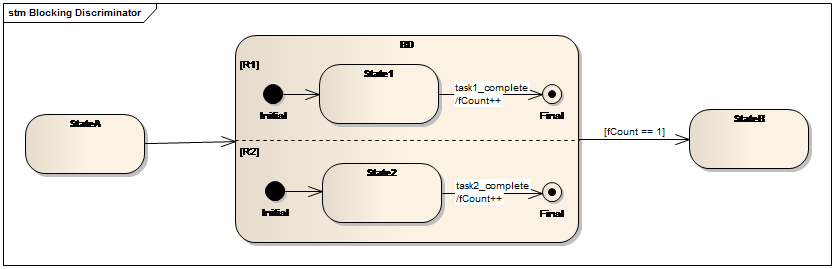
Fig. 9.Blocking discriminator pattern
3.6 Cancelling Discriminator
The cancelling discriminator is used to pass the control-flow to the subsequent branch when the first parallel branch triggered from the and-split construct is completed and also cancel the execution of the tasks in the other parallel branches. Note that only the first completed branch is important.The business object-oriented modeling approach supports this pattern by means that withdraw the task instances in the uncompleted branches.
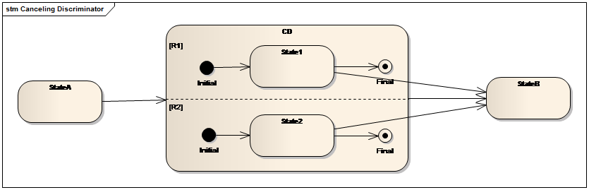
Fig. 10.Cancelling discriminator pattern
3.7 Structured Partial Join
The structured partial join pattern provides a means of merging two or more parallel branches (say m) into a single branch where m is less that the number of parallel branches. The completions of the remaining parallel branches (say n-m) do not result in the execution of the subsequent tasks.The business object-oriented modeling approach uses a variable fCount to record the completion of a parallel branch. As shown in Fig.11, when fCount equals to the specific number, here is two, the transition from the parallel state SPJ to StateB is triggered. One point should be noticed is that in the business object-oriented modeling approach, the remaining tasks in the remaining parallel branches are all canceled instead of letting them execute until completed, since leaving a state means the task in that state is disabled and cannot be executed. So actually we cannot totally support this pattern.
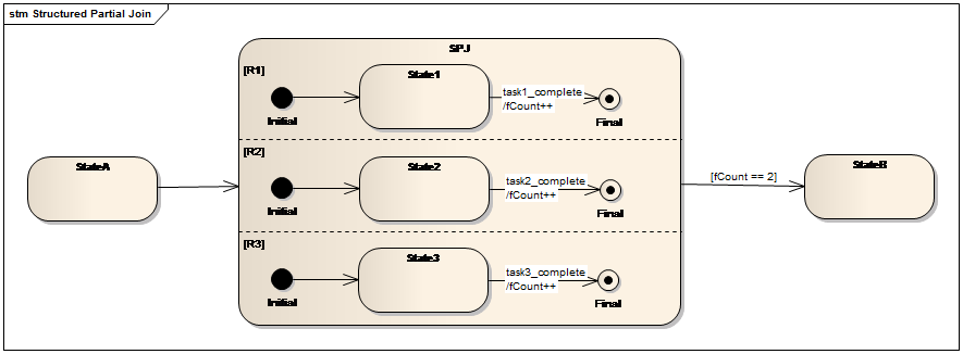
Fig. 11.Structured partial join pattern
3.8 Blocking Partial Join
The blocking partial join pattern is the variant of the structured partial pattern which is used when there are concurrent execution instances of the same process model in the environment. It is the combination of the blocking discriminator pattern and the structured partial join pattern.We cannot totally support this pattern as the same reason we have announced in the above.
3.9 Cancelling Partial Join
The cancelling partial join pattern merges two or more parallel branches (say m) into a single branch where m is less that the number of parallel branches (say n). The merge of these m branches also cancel the execution of the remaining parallel branches (say n-m).The business object-oriented modeling approach uses a variable fCount to record the completion of a parallel branch. As shown in Fig.13, when fCount equals to the specific number, here is two, the transition from the parallel state SPJ to StateB is triggered. Meanwhile, other tasks are cancelled.
As a result, the business object-oriented modeling approach supports the cancelation and retention of the remaining parallel branches.
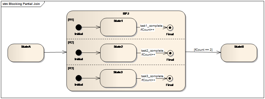
Fig. 12.Blocking partial join pattern
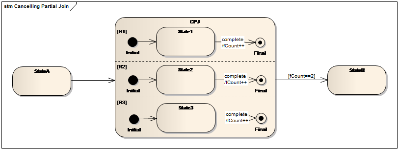
Fig. 13.Cancelling partial join pattern
3.10 Generalized AND-Join
The generalized AND-join pattern merges the parallel branches when all the triggered branches are completed. The business object-oriented process modeling approach describes this pattern by means of the parallel state. When a parallel branch is completed, it will wait for the completions of all the other parallel branches before exiting the parallel state.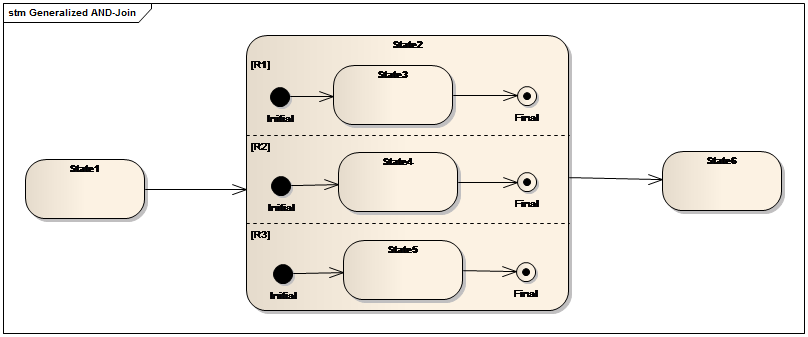
Fig. 14.Generalized AND-join
3.11 Local Synchronizing Merge
The general synchronizing merge pattern merges the parallel branches. The determination of how many parallel branches require synchronization is made on the basis on information locally available to the merge construct dynamically. The business object-oriented process modeling approach describes this pattern same as the structured synchronizing merge pattern.3.12 General Synchronizing Merge
The general synchronizing merge pattern merge the parallel branches when either (1) each active parallel branch has been completed or (2) it is not possible that any branch that has not yet been completed will be completed at any future time. The basis of this pattern is the implicit termination of some parallel branches. However, the life cycle of a business object must have a single Final state indicating the end of the life cycle. Semantically any state must have one path to that Final state. Hence a business object-oriented process model allows no implicit termination states which means there are no transitions leaving from that state. Therefore, the general synchronizing merge pattern is not supported.3.13 Thread Merge
This pattern provides a means of merging multiple execution threads of a branch within a given process instance. It is a counterpart to the Thread Split pattern which creates multiple execution threads along the same branch. The business object-oriented modeling approach supports thread split pattern and thread merge pattern together by creating a nominated number of execution threads of a task and merging them into a single thread when they are completed.3.14 Thread Split
This pattern provides a means of triggering multiple execution threads of a task with-in a given process instance. It is a counterpart to the Thread Merge pattern which merges multiple execution threads along the same branch. The business object-oriented modeling approach supports thread split pattern and thread merge pattern together by creating a nominated number of execution threads of a task and merging them into a single thread when they are completed.
4 Multiple Instance Patterns
This series of patterns describe multiple instances of the same task are created in a business process based on different situations.
4.1 Multiple Instances without Synchronization
This pattern describes situation in which multiple instances of a given task can be created and the number of instances is known before the task is executed. These instances are independent of each other and run concurrently within the context of the process instance. There is no need to synchronize them when they are completed.The business object-oriented modeling approach supports this pattern as shown in Fig.15. When entering State2, the task in the entry action will be executed. The re-quired number of the instances is obtained from the parameters of the event generated by the completion of the task in State1.
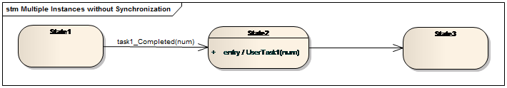
Fig. 15.Multiple instances without synchronization pattern
4.2 Multiple Instances with a Priori Design-Time Knowledge
This pattern describes a situation in which multiple instances of a given task can be created and the number of instances is known at design time. These instances are independent of each other and run concurrently. The completions of the task instances must be synchronized before the processing of the subsequent branch.The business object-oriented modeling approach supports this pattern as shown in Fig.16 When entering State2, the task in the entry action will be executed. The required number of the instances is given in the business data at design time. We use a variable fCount to count for the completion of each task instance. When the value of fCount is equal to the number of the instance, the synchronization is executed and the transition to State3 is triggered.
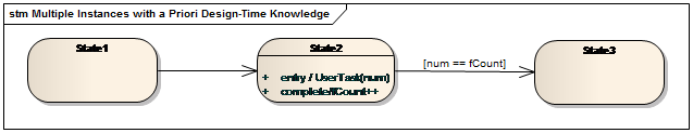
Fig. 16.Multiple instances with a priori design-time ksowledge
4.3 Multi Instances with a Priori Run-Time Knowledge
This pattern describes a situation in which multiple instances of a given task can be created and the number of instances is known during run time, but before the first of the task is executed. These instances are independent of each other and run concurrently. The completions of the task instances must be synchronized before the processing of the subsequent branch.The business object-oriented modeling approach describes this pattern as shown in Fig.17. When entering State2, the task in the entry action will be executed. The required number of the instances is obtained from the parameters of the event generated by the completion of the task in State1. We use a variable fCount to count for the completion of each task instance. When the value of fCount is equal to the number of the instance, the synchronization is executed and the transition to Ssate3 is triggered.
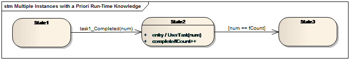
Fig. 17.Multi instances with a priori run-time knowledge
4.4 Multiple Instances without a Priori Run-Time Knowledge
This pattern describes a situation in which multiple instances of a given task can be created. The required number of instances may depend on a number of runtime factors and cannot be determined until the last instance of that task is completed. At any time, whilst multiple instances are running, it is possible for additional instances of the same task to be created.The business object-oriented modeling approach utilizes the combination of external events and internal transitions to implement this pattern. As shown in Fig.18, when entering State2, the instances of UserTask2 are created. The required number of the instances depends on a number of runtime factors. For example, the number may be the parameters of the event generated by the completion of the task in State1.
While in State2, if the user sends an event named newInstance from the external system, an internal transition is triggered and an additional instance is created. Meanwhile, the variable num is increased by one. When a task instance is completed, an event named complete is generated and the internal transition is triggered. The action on this transition is to increase the variable fCount by one. When the value of fCount is equal to the number of the instances which are actually created, the synchronization is executed and the transition to State3is triggered.
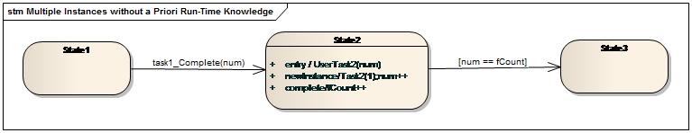
Fig. 18.Multi instances without a priori run-time knowledge
4.5 Static Partial Join for Multiple Instances
This pattern describes a situation in which multiple instances of a given task can be created and the number of instances is known during run time, but before the first of the task is executed. These instances are independent of each other and run concurrently. Once a specific number task instances have been completed, the next task is triggered. Subsequent completions of the remaining instances are inconsequential. However all instances must have been completed in order for the join construct to reset and be subsequently re-enabled.The business object-oriented modeling approach describes this pattern as shown in Fig.19. When entering State2, the task in the entry action will be executed. The required number of the instances is obtained from the parameters of the event generated by the completion of the task in State1. We use a variable fCount to count for the completion of each task instance. When the value of fCount is equal to the number of the instance, the synchronization is executed and the transition to State3 is triggered. Other task instances of UserTask2 will be cancelled. One point in the business object-oriented modeling approach that is different from this pattern is that the remaining task instances are all canceled instead of letting them execute until completed, since leaving a state means the task in that state is disabled and cannot be executed.

Fig. 19.Static partial join for multiple instances
4.6 Cancelling Partial Join for Multiple Instances
This pattern describes a situation in which multiple instances of a given task can be created and the number of instances is known during run time, but before the first of the task is executed. These instances are independent of each other and run concurrently. Once a specific number of the task instances have been completed, the next task is triggered. This pattern differs from the static partial join for multiple instances pattern in that the remaining instances are cancelled.Since the business object-modeling approach only supports the cancellation of remaining task instances, the description of this pattern in the business object-oriented modeling approach is the same as the static partial join for multiple instances pattern.
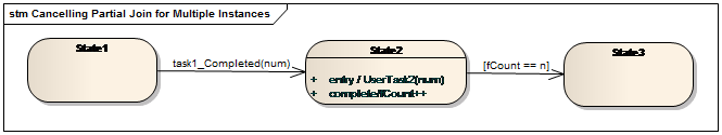
Fig. 20.Cancelling partial join for multiple instances
4.7 Dynamic Partial Join for Multiple Instances
This pattern describes a situation in which multiple instances of a given task can be created. The required number of instances may depend on a number of runtime factors and cannot be determined until the last instance of that task is completed. At any time, whilst multiple instances are running, it is possible for additional instances of the same task to be created. A completion condition is specified which is evaluated each time a task instance is completed. Once the completion condition evaluates to true, the next task in the process is triggered. Subsequent completions of the remaining task instances are inconsequential and no new instances can be created.The business object-oriented modeling approach utilizes the combination of external events and internal transitions to implement this pattern. As shown in Fig.21, when entering State2, the instances of UserTask2 are created. The required number of the instances depends on a number of runtime factors. For example, the number may be the parameters of the event generated by the completion of the task in State1.
While in State2, if the user sends an event named newInstance from the external system, an internal transition is triggered and an additional instance is created. Meanwhile, the variable num is increased by one. When a task instance is completed, an event named complete is generated and the internal transition is triggered. The action on this transition is to increase the variable fCount by one and send an event E. The condition of the transition from State2 to State3 is evaluated each time a task instance is completed. When it becomes true, the synchronization is executed and the transition to State3is triggered. One point in the business object-oriented modeling approach that is different from this pattern is that the remaining task instances are all canceled instead of letting them execute until completed, since leaving a state means the task in that state is disabled and cannot be executed.
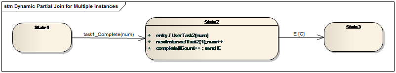
Fig. 21.Dynamic partial join for multiple instances
5 State-based Patterns
This series of patterns describe how the behavior of a business process may be affected by factors from external environment. Since the business object-oriented modeling approach is based on statecharts which is event-driven and state-based, all the five patterns in this class are supported.
5.1 Deferred Choice
The deferred choice pattern is similar to the exclusive choice pattern that only chooses one path from the alternative paths. However, the choice mechanism is different. The deferred choice pattern is based on interaction with the external environment. When the process instance receives an event from the external environment, the decision is made and other alternative paths are withdrawn.The business object-oriented modeling approach describes this pattern by generating an event from the external systems, such as an event sent by the user, timeout event, environment data etc. When an event is received, the proper transition is triggered and other alternative states won’t be entered.
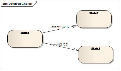
Fig. 22.Deferred choice pattern
5.2 Interleaved Parallel Routing
This pattern describes a set of tasks that must be executed with respect to their partial ordering. Although there is a word “parallel” in the name of this pattern, tasks in that set must be executed in a sequential order and it is not possible to initiate one task during the execution of another task.As shown in Fig.23, there is a Null state between the sub states in each parallel branch which is used to wait for events to be occurred. When the transition from StateA to IPR is triggered by event complete_TaskA, an event is sent from the set {e1, e2, e3, e4} randomly depend on the external environment and the current state of the process model. When entering IPR, if e1 is chosen, the first parallel branch is triggered by e1 and moves to State1. While Task1 is being executed, the other two branches stay in Null waiting for e2 or e3 to be sent. When Task1 is completed, the transition from State1 to the Final state is triggered and an event from the set {e1, e2, e3, e4} is sent randomly depend on the external environment and the current state of other parallel branches. Here if e2 is chosen to be sent, when the second branch takes the transition from State2 to Null, an event from the set {e1, e2, e3, e4} is sent ran-domly depend on the external environment and the current state of other parallel branches. Here only e3 or e4 can be generated since the first parallel branch has arrived at its final state and the third branch is still in the Null state. The transition from the concurrent state to StateB is triggered when all the parallel branches are at their Final states.
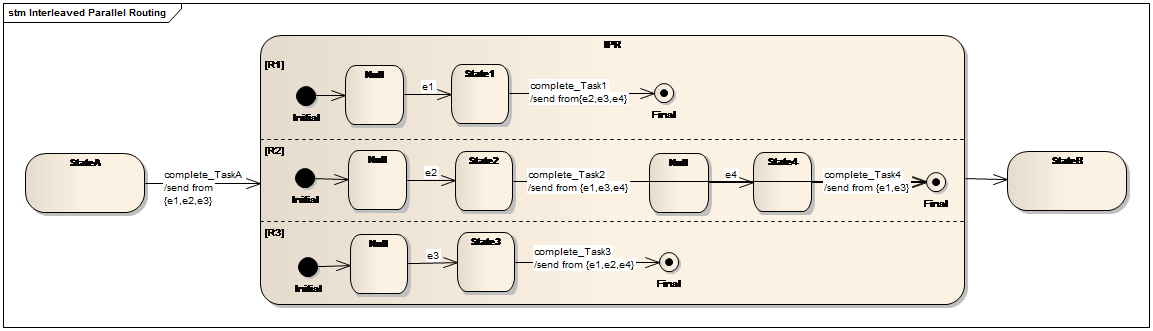
Fig. 23.Interleaved parallel routing pattern
5.3 Milestone
The description of the milestone pattern is that the task is executed only when the process instance is in a specific state (typically a parallel branch). The state is assumed to be a specific execution point (also known as a milestone) in the process model. If the process instance has progressed beyond this state, then the task cannot be executed now or at any future time.The business object-oriented modeling approach describes this pattern by the test condition in (somestate) within a concurrent state, which means that if some parallel branch is in a specific state, the nominate transition in another parallel branch is triggered. As shown in Fig.24, the transition from State2 to State3 is triggered only when the current state of the concurrent state StateP is State3. In other words, the task in State4 is executed only when the first parallel branch is in State3.
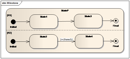
Fig. 24.Milestone pattern
5.4 Critical Section
The description of critical section pattern is that limits the concurrent execution of two or more critical sections of a process. Once the tasks in one "critical section" start to execute, it must complete before another "critical section" can start to execute.The business object-oriented modeling approach implements this pattern as shown in Fig.25. When the transition from StateA to StateCS is triggered, an event from the set {e1, e2} is sent to the process model. Therefore only one parallel branch will be processed and another parallel branch waits for the trigger event. If the top parallel branch is executed first, it will send e2 when it moves to the Final state. At this time the branch below the first branch starts processing. When it completes, it will send e1. Note that e1 is ignored since at this time the above parallel branch is at its Final state.
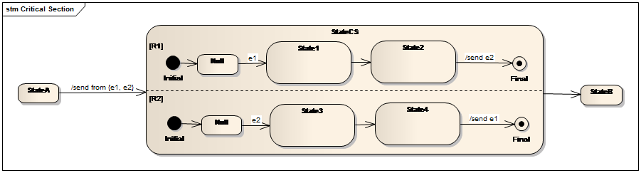
Fig. 25.Critical section pattern
5.5 Interleaved Routing
The interleaved routing pattern allows a set of tasks to be executed in any order but no two tasks can be executed at the same time. The next task in the process can be executed after each task in this set has been executed once.As shown in Fig.26, there is a Null state behind the initial state in each parallel branch which is used to wait for events to be occurred. When the transition from Sta-teA to IR is triggered by event complete_TaskA, an event is sent from the set {e1, e2, e3, e4} randomly. When entering IR, if e1 is chosen, the first parallel branch is triggered by e1 and moves to State1. While Task1 is being executed, the other two branches stay in Null waiting for e2 or e3 to be sent. When Task1 is completed, the transition from State1 to the Final state is triggered and an event from the set {e2, e3} is sent randomly depend on the current state of other parallel branches. Here if e2 is chosen to be sent, when the second branch takes the transition from State2 to the Final state, an event from the set {e1, e3} is sent randomly depend on the current state of other parallel branches. Here only e3 can be generated since the first parallel branch has arrived at its final state. The transition from the concurrent state to StateB is triggered when all the parallel branches are completed.
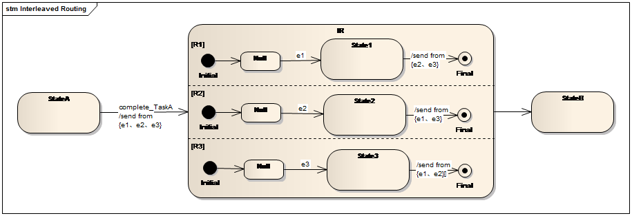
Fig. 26.Interleaved routing pattern
6 Cancellation and Force Completion Patterns
Several of the patterns above have variants that utilize the concept of activity cancellation where task instances are withdrawn. Various forms of exception handling in processes are also based on cancellation concepts. This series of patterns describe five cancellation patterns.
6.1 Cancel Task
The cancel task pattern describes the ability to withdraw a task which has been enabled or is already executing.The business object-oriented modeling approach describes this pattern as shown in Fig.27. The transition from State2 to State3 or State4 is a race relationship between the cancelTask event and the completion of the task instance.
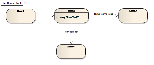
Fig. 27.Cancel task pattern
6.2 Cancel Case
This pattern is an extension of the cancel task pattern that an entire process instance is removed.The business object-oriented modeling approach describes this pattern as shown in Fig.28. Each state has a transition to the Final state triggered by the cancelCase event. When a cancelCase event is generated, no matter which state the process instance is in, the process instance will be completed immediately.
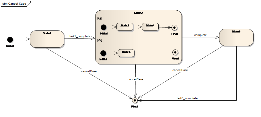
Fig. 28.Cancel case pattern
6.3 Cancel Region
The cancel region pattern describes cancelling a set of tasks in a process instance.The business object-oriented modeling approach describes this pattern as shown in Fig.29. When a cancel event is generated and the process instance is in State3 or State4 or State5, the transition from State2 to State8 is triggered by the cancel event and all the executing task instances or enabling tasks in these states are withdrawn.
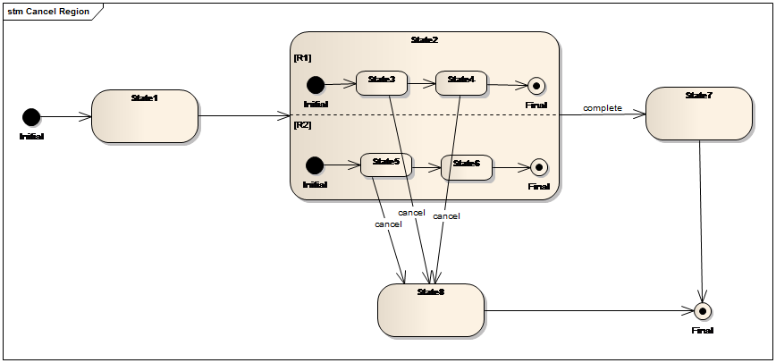
Fig. 29.Cancel region pattern
6.4 Cancel Multiple Instance Task
This pattern provides a means of cancelling a multiple instance task at any time during its execution such that any remaining instances are cancelled. Task instances that have already completed are unaffected by the cancellation.The business object-oriented modeling approach describes this pattern as shown in Fig.30. In State2, 500 instances of UserTask2 are created and assigned to users. If the task is not completed before the given time or some other exception occurs during executing, the cancelTask event is generated. The transition from State2 to State4 is triggered to the cancelTask event and all the remaining task instances are withdrawn.
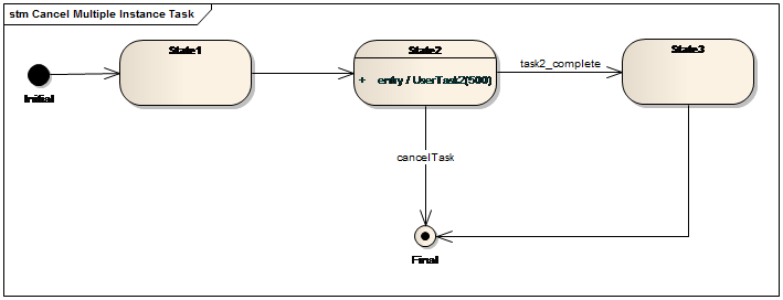
Fig. 30.Cancel multiple instance task
6.5 Complete Multiple Instance Task
This pattern provides a means of forcibly completing a multiple instance task at any time during its execution such that any remaining task instances are cancelled and the thread of control is passed to subsequent tasks.The business object-oriented modeling approach describes this pattern as shown in Fig.31. In State2, 500 instances of UserTask2 are created and assigned to users. If the task is not completed after an hour, the transition from State2 to State3 is triggered and the task in State3 is executed.
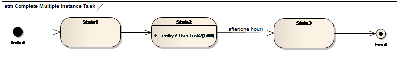
Fig. 31.Complete multiple instance task
7 Iteration Patterns
The following patterns deal with capturing repetitive behavior in a workflow.
7.1 Arbitrary Cycles
This pattern provides a mechanism to allow repeating cycles in a process model in an unstructured way. The loop has more than one entry or exit points.The business object-oriented modeling approach describes this pattern as shown in Fig.32. There are two entry points: State4 and State5.
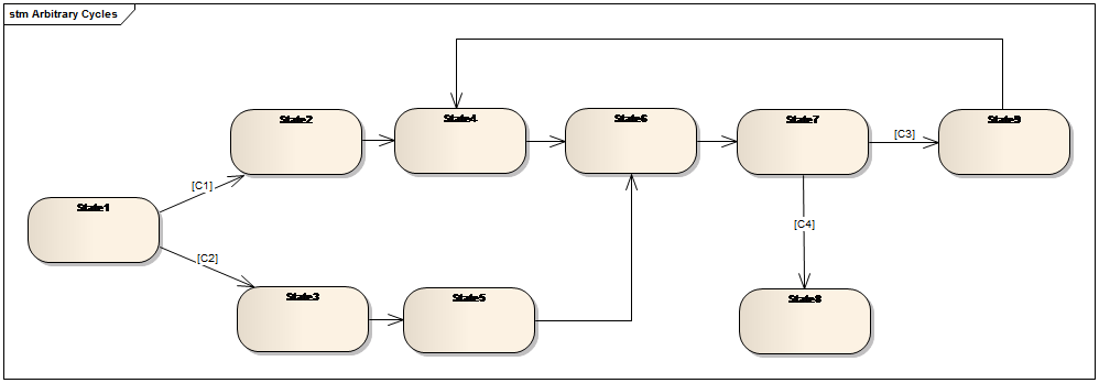
Fig. 32.Arbitrary Cycles
7.2 Structured Loop
This pattern provides the ability to execute a task or sub-process repeatedly. The difference between the structured loop pattern and arbitrary cycles pattern is that in this pattern the loop has either a pre-test or post-test condition to determine the beginning and end of the loop. Meanwhile, the loop has a single entry and exit point.The business object-oriented modeling approach describes this pattern with a pre-test as shown in Fig.33.
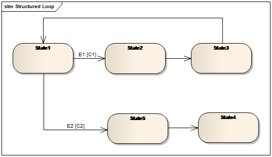
Fig. 33.Structured loop
7.3 Recursion
This pattern describes the ability of a task to invoke itself during its execution or an ancestor in terms of the overall decomposition structure with which it is associated.The business object-oriented modeling approach describes this pattern by means of creating new business objects during the processing of an existing business object.
8 Termination Patterns
8.1 Implicit Termination
A given process instance should terminate when there are no remaining work items that are able to be done either now or at any time in the future and the process instance is not in deadlock.The life cycle of a business object must have a single Final state indicating the end of the life cycle. Semantically any state must have one path to that Final state. Hence a business object-oriented process model allows no implicit termination states which means there are no transitions leaving from that state. Therefore, the implicit termination pattern is not supported.
8.2 Explicit Termination
A given process (or sub-process) instance must terminate when it reaches a nominated end node. When this end node is reached, any remaining tasks in the process instance are cancelled and the overall process instance is recorded as having completed successfully.The business object-oriented modeling approach describes this pattern by means of the Final state. When the task in State4 is completed, the transition from the parallel state to the Final state is triggered and the tasks remained in state2 are cancelled.
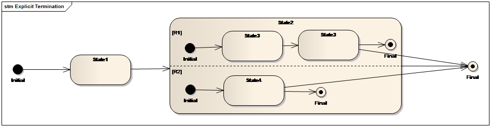
Fig. 34.Explicit Termination
9 Trigger Patterns
The following patterns deal with the external signals that may be required to start certain tasks.
9.1 Transient Trigger
This pattern provides the ability for a task instance to be triggered by a signal from another part of the process or from the external environment. These triggers are transient and are lost if not acted on immediately by the receiving task.The business object-oriented modeling approach describes this pattern by means of default event. If an event is generated, the event will be utilized only when the current state of the business object is waiting for this event. Otherwise it will be invalid.
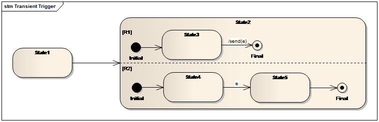
Fig. 35.Transient trigger
9.2 Persistent Trigger
This pattern provides the ability for a task to be triggered by a signal from another part of the process or from the external environment. These triggers are persistent in form and are retained by the process until they can be acted on by the receiving task.The business object-oriented modeling approach describes this pattern by means of delay events. If the event is a delay event, then the event will be retained until the business object arrives at a state which can trigger it.